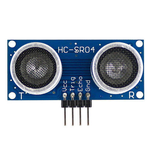
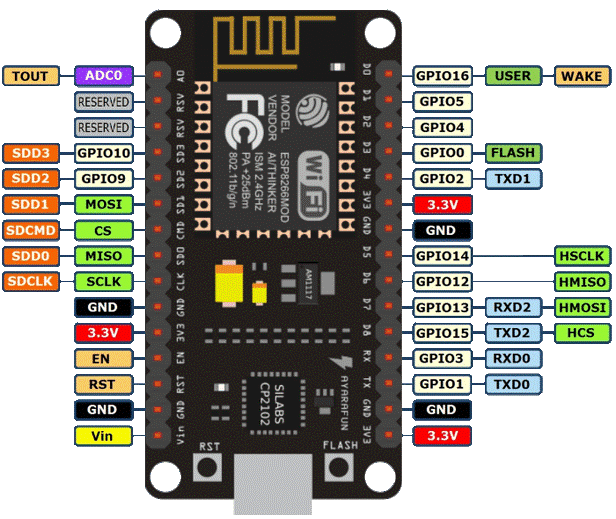
ULTRASONIC SENSOR INTERFACING WITH NODEMCU
In this project a NodeMCU board that has ESP8266 microcontroller used to determine the distance of an object using an ultrasonic sensor that has trigger and echo pins placed on it. The distance is calculated and displayed in the serial monitor.
Synopsis

In this project a NodeMCU board that has ESP8266 microcontroller used to determine the distance of an object using an ultrasonic sensor that has trigger and echo pins placed on it. The distance is calculated and displayed in the serial monitor.

Description


ULTRASONIC sensor

This sensor is used to measure the distance between the object and the sensor. The ultrasonic sensor has 4 pins, one for power and one for ground one is trigger pin and an echo pin. This sensor measures the distance by emitting ultrasonic waves from the trigger pin and then receives the emitted waves through echo pin. Thus, the waves travel to the object and reflects back to the echo pin. Hence in this process, the sound waves travel twice the distance that is one from trigger pin to object and then from object to echo pin. Distance=Speed of sound*time Speed of sound = 340m/s. = 3.4*10^6 mm/s. For Micro seconds, speed of sound = 0.034mm/micro Sec. Thus, distance for ultrasonic sensor can be determined with the formula mentioned below: Distance=(time*0.034)/2 Where, time = the duration taken by the ultrasonic wave return back to echo pin from trigger pin.

NodeMCU

A NodeMCU is a development board with an inbuilt Wi-Fi module in it. It is a basic and cost-efficient board to carry out projects using internet of things. The NodeMCU has ESP8266 microcontroller unit in it. The operation of this microcontroller is controlled with the programs used in Arduino thus making it very easier to use and also to learn basic IoT projects. This board has inbuilt 2.4GHz antenna to receive Wi-Fi functions. This board has a memory of 4mb to store the data acting as ROM and 64Kb of RAM. This board operates at 3.3 volts and it is mandatory to operate the board at this voltage and not more than that as increasing the input voltage in this board may damage few GPIO pins (general input-output pins).


Pin Configuration

1. Vin: 3.3V can be provided at this pin as the supply to power on the board. This pin is used to power on the entire microcontroller.

2. GND: This pin is connected to the negative terminal of the battery.

3. RST: This pin resets the microcontroller and clears the memory.

4. EN: This pin is used to enable the operation of microcontroller.

5. 3V3: This pin provides 3V output and this can be used to power up some sensor units connected to the microcontroller.

6. SD1, CMD, SD0, CLK: These pins are used in SPI communication, that is it is used to transfer the signals between two microcontrollers, Rx and Tx modules with asynchronous transmission.

7. SD3, SD2: These pins can also function as asynchronous transmission or as GPIO pins.

8. RSV: These are two reserved pins used by the microcontroller and cannot be used in connecting any external circuits to it.

9. A0: This microcontroller only has one analog pin for Analog communication. This A0 pin is used in analog signal communication.

10. GPIO 1 – 16: This controller board has 16 input-output pins which be used as input or output pin based on the programming.

11. GP10 1, 3, 13, 15: This microcontroller has 2 UART communication pins, RX0, TX0 (GPIO 1 & GPIO 3) and RX1, TX1 (GPIO 13, GPIO15).

Schematic


Code

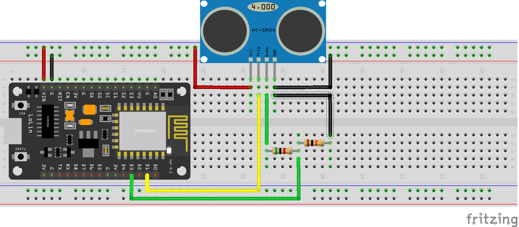
const int trigPin = D1;
const int echoPin = D3;
long duration;  int distance; // VARIABLES
void setup() {
pinMode(trigPin, OUTPUT);     // TRIGPIN IS OUTPUT
pinMode(echoPin, INPUT);      // ECHO PIN IS INPUT
Serial.begin(9600);           // 9600 BITS TRANFERING TO PC PER SECOND
}
void loop() {
digitalWrite(trigPin, LOW);   // SENDING LOW PULSE FOR 2uSECONDS TO TRIGGER
delayMicroseconds(2);
digitalWrite(trigPin, HIGH);  // SENDING HIGH PULSE FOR 10uSECONDS TO TRIGGER
delayMicroseconds(10);
digitalWrite(trigPin, LOW);   
duration = pulseIn(echoPin, HIGH); // TO READ THE PULSE WHICH RETURN BACK THROUGH ECHO PIN
distance= duration*0.034/2;        // CALUCATING DISTANCE BASED ON SOUND VELOCITY

Serial.print("Distance: ");
Serial.println(distance);
}

Error message here!

Show Error message here!


Forgot your password?

Error message here!

Send OTP

Error message here!

Show Error message here!


Lost your password? Please enter your email address. You will receive a password you Need.

Send Error message here!


Back to log-in

Close